SCI. HOBBYIST  
MISCONCEPTIONS  
ELECTR. HOBBYIST  
GOOD STUFF  
NEW STUFF  
SEARCH

CAPACITOR COMPLAINTS
1996 William J. Beaty

Date: Sat, 8 Jun 1996 14:17:53 -0700 (PDT)
From: "Bill Beaty"
To: ELECTRON @ CCTR.UMKC.EDU
Subject: Re: light bulbs

On Thu, 6 Jun 1996, Rader William E wrote:
> On a more serious note (for every one out there),
> I would like to know how a capacitor REALLY works. I have read
> as many texts as you have but don't you believe them !
> If you have access to a high voltage generator (Wimherst sic )
> and a take-apartable Leyden jar please play(i mean experiment)
> with these and tell me how a capacitor really works

I have beefs with textbook explanations of capacitors too. "Capacitors store charge?" No! Flat out wrong! Wait and hear me out, I'm not insane.

;)

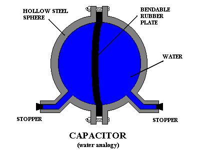
Thick iron sphere, rubber plate down the middle, both 
sides full of water

When we "charge" a conventional metal-plate capacitor, the power supply pushes electrons into one plate, and the fields from these extra electrons reach across the gap between the plates, forcing an equal number of electrons to simultaneously flow out of the other plate and into the power supply. This creates opposite areas of imbalanced charge: one plate has less electrons and excess protons, and the other plate has more electrons than protons. Each individual plate does store charge.


However, if we consider the capacitor as a whole, no electrons have been put into the capacitor. None have been removed. The same number of electrons are in a "charged" capacitor as in a capacitor which has been totally "discharged." Yes, a certain amount of charge has been forced to flow momentarily during "charging," and a rising potential difference has appeared. But the current is directed through the capacitor, and the incoming electrons force other electrons to leave at the same time. Every bit of charge that's injected into one terminal *must* be forced out of the other terminal at the same time. The amount of charge inside the capacitor never changes. The net charge on each plate is cancelled by the opposite charge on the other plate. Capacitors are never "charged" with electric charge!

Think about this:

When "charging" a capacitor, a momentary current causes the voltage to rise. Volts times electron-flow equals energy-flow ( V x I = P). Therefore during a momentary current through a capacitor, there is a joules-per-second transfer of energy from the power supply into the capacitor.

Therefore, during the "charging" process, energy is placed into the capacitor. Capacitors store energy, not charge. When we "charge" a capacitor, we give it a charge of energy. But because we use the word "charge" to refer both to electric charges and also to quantities of energy, our capacitor explanations are nearly impossible to understand. "Charging" a capacitor means injecting electrical energy into the device.

Similar trouble is caused when we say that we "charge" a battery. We charge a battery with some energy in the form of stored chemical fuel, but we do this by pumping electric charge through the battery and none of it builds up inside. Fuel-chemicals build up inside. Charge does not.

It's all terribly confusing. What are students to think if we tell them that "charging a battery" doesn't store any charge, yet charge must flow through the battery if we want to charge it! Ugh. The word "charge" has far too many meanings. In Science, this is always a Very Bad Thing.

[ad]

Another situation is a bit, less misleading: think of the word "charge" as applied to gunpowder. A charge is placed in an old cannon, followed by a cannonball. It would be silly to assume that, because we've "charged" the cannon, the cannon now has an electrical charge. Yet whenever we state that we've "charged" a capacitor, we do assume that an electrical charge has been stored inside. This is just as silly as mistaking gunpowder for electrostatic charges. Charging a capacitor (or a battery) is like charging a cannon; in both situations we are inserting energy, not electrical charge.

Here's yet another way to visualize it. Whenever we "charge" a capacitor, the path for current is through the capacitor and back out again. The extra electrons on one plate force electrons to leave the other plate, and vice versa. Visualize a capacitor as being like a belt-driven wind-up motor. If we shove the rubber belt along, the spring-motor inside the capacitor winds up. If next we let the rubber belt go free, the wound-up spring inside the motor drives the belt backwards, and the spring becomes "discharged." But no quantity of "belt" is stored inside this motor. The belt flows through the device, and we wouldn't want to label this motor as a "machine which accumulates rubber." Yet this is exactly what we're saying whenever we state that capacitors "store charge."

One more try. Capacitors store charge in the same way that resistors store charge, and inductors store charge. Inductors are full of mobile electrons, inductors are devices for storing charge!!!! Nope. An inductor isn't a bucket for accumulating electrons, and neither is a capacitor. Instead, both types of component behave like piece of wire But capaictors are magical wires which, whenever we run a current along it, the total charge inside the wire stays constant, but a voltage (and a charge imbalance) appears at the two ends.

My favorite capacitor analogy is a heavy hollow sphere which is completely full of water and is divided in half with a flexible rubber plate through its middle. Hoses are connected to the two halves of the thick irong sphere, and they act as connecting wires. The rubber plate is an analogy for the dielectric. The two regions of water symbolize the capacitor plates.

Imagine that the rubber plate is flat and undistorted at the start. If I connect a pump to the two hoses and turn it on for a moment, the pump will pull water from one half of the iron sphere and simultaneously force it into the other. This will bend the rubber divider plate more and more. The more the plate bends, the higher the back-pressure the plate exerts, and finally the pressure-diff will grow strong enough that the pump will stall. Next I seal off the hose connections and remove the pump. I now have created a "charged" hydraulic capacitor.
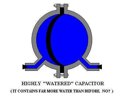
Now the rubber plate is bent sideways, so one side has more water

Now think: in this analogy, water corresponds to electric charge. How much water have I put into my iron sphere? None! The sphere started out full, and for every bit of water that I took out of one side, I put an equal amount into the other at the same time. Same as when running a current through a conductor. When the pump pushed water into one side, this extra water also forced some water out of the other side. No water passed through the rubber, instead there was some rubber-current in the divide. Even so, essentially I drove a water current through my hydraulic capacitor, and this current pushed on the rubber plate and bent it sideways. Where is the energy stored? Not in the water, but in the potential energy of the stretched rubber plate. The rubber plate is an analogy to the electrostatic field in the dielectric of a real capacitor.

It would be misleading to say "this iron sphere is a device for accumulating water." And neither say "this sphere can be charged with water, and the stored water can be retrieved during discharge." Both statements are wrong. No water was injected into the sphere while it was being "charged." (And when I wind up an old watch, am I "storing steel" inside it, putting more iron into its spring? Lol.

Imagine that I now connect a single length of pre-filled hose between the two halves of my "energized" water sphere. As soon as the last connection is complete, the bent rubber plate will drive a sudden immense spurt of water through this already-full hose. Water from one side will be pushed into the other side, and the rubber plate will relax. I've discharged my hydraulic capacitor. How much water has been removed from the sphere? None! A momentary current has flowed through the sphere device, and the rubber plate is back to the middle again, and the water has become a bit warm through friction against the surfaces of the hose. The stored energy has been "discharged," but no water has escaped. The hydraulic capacitor has lost its energy, but still contains the same amount of water.
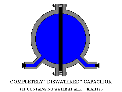
Now the water has equalized, and the rubber plate has straightened again.

I never really understood capacitors until I started trying to construct proper water-analogies for them. Then I discovered that my electronics and physics classes had sent me down a dead-end path with their garbage about "capacitors store electric charge." Since my discovery, I've gained significantly more expertise in circuit design, which leads me to a sad thought. Maybe the more skilled of electrical engineers and scientists gain their extreme expertise not through classroom learning. Instead they gain expertise in spite of our K-12 classroom learning. Maybe the experts are experts only because they have fought free of the wrong parts of grade school science, while the rest of us are still living under the yoke of the many physics misconceptions we were carefully taught in early grades.

[Hey, M. Steinberg's C.A.S.T.L.E. electricity curriculum uses the same analogy! In all my search of textbooks, this is the only one I've found. In section 3.9, students construct a 2-chambered air capacitor with a balloon membrane stretched between the two chambers. To "charge" it we take air from one side and pump it into the other. ]

[Hey^2!!! I just found that Oliver Lodge was building mechanical analogies for Maxwell's descriptions of EM fields and circuits... and for an 1880 lecture he built a capacitor hydraulic analogy consisting of a water-filled sphere with rubber! His was a glass sphere containing a smaller balloon, both full of water with no bubbles.]

LINKS

Extra notes:

Capacitors store just as much charge as coils do! In both devices the total amount of charge stays constant. Whenever we force charge into the first capacitor plate, equal charge must flow out of the second capacitor plate. The path for current is through. Capacitors and inductors are both components for storing electromagnetic energy. They're two sides of the same EM phenomenon: a coil stores energy in a volume containing a magnetic field, while a capacitor does something similar with electric fields. Coils are "discharged" by interrupting a large current and collapsing the b-field, while capactors are discharged by shorting-out a large voltage and collapsing the e-field. Neither stores any "electricity" (unless by the word 'electricity' you mean magnetic field?) Of course we can place a coil atop an insulating platform, then use a VandeGraaff generator to give your coil a large net-charge! You can do the same with a big electrolytic capacitor too. :)


Bill Beaty here again. Two points:

First, the heated topic about currents being impossible between capacitor plates ...seems to be about Vacuum Capacitors, not capacitors in general. Modern capacitors are quite different than vacuum capacitors, where inside a modern dielectric we'll find a large electron-current. Relative Permittivity can be seen as a ratio between the small Maxwell's displacement current inside a vacuum, versus the larger polarization current (electron flow: the shifting of electrons) in the ferroelectric PZT material. The dielectric constant in modern ceramic capacitors is above 2,000, so the vast majority of the current in the dielectric is a genuine charge-flow, a real current caused by shifting the electrons in the ferroelectric ceramic. The Maxwell displacement current of the vacuum is insignificant: well below 1%.

Second: it might help to ask whether, down at the micro level inside a metal, in the space BETWEEN the electrons, is there any electric current? If there is, that's a current in empty space. And in that case, there's certainly a current in the space between the metal plates of a vacuum capacitor. Or said differently: if we have a current-sensor, and a charged particle approaches and passes it, does our sensor indicate an extremely brief pulse, where the pulse-width is associated with the diameter of the charged particle? Or instead does our sensor see each moving particle as being very large and "fuzzy," so that the measured current is found in the fields surrounding each particle, and the current extends forwards and back from the particle location? A clamp-on current meter (Rogowski coil) doesn't detect the actual particles or their motions. Instead it detects changing flux-linkage. It thinks that amperes are made out of fields. A clamp-on sensor would report that each charged particle is indeed large and fuzzy, and the current exists in the empty spaces between the flowing charges. Current is not only found on the flowing particles' surfaces where the moving charge actually resides. So, a clamp-on sensor would 'see' currents in a vacuum-capacitor's empty gap. The changing fields are in that gap, so that's where the current appears.

Only two points? Third point, suppose we construct a capacitor where the dielectric takes the form of a long rod: much thicker than the diameter of capacitor plates. Use a long narrow PZT lead-zirconate- titanate rod with tiny capacitor plates attached to its circular ends. Now apply some 27MHz amperes. Do you still insist that the current within this rod is zero? Really? It's not. Next, suppose we obtain a coil-shaped spiral rod of PZT. A ceramic "ferroelectric coil." If we apply some RF amperes through this spiralled dielectric, we'll certainly detect a strong magnetic field surrounding the device. Our capacitor's dielectric is now a coil. If the current is supposedly zero within all capacitor dielectrics (as some people angrily insist,) how can we explain this? Simple: capacitor dielectrics do contain current after all. The value of current in the dielectric is exactly the same as the amperes in the capacitor leads.


Capacitors: physicists vs. engineers

> For the charge to flow in a circuit, there has to be a closed path.
> Right, sir! Please correct me if I am wrong.

No, there must be a closed path ONLY if the charges must flow continously in the circuit forever (pure DC). But if the charges flow briefly, or if they flow back and forth (AC), then an open path is sometimes acceptable.

For example, with a metal rod 1 meter in length, it is possible to create a standing wave of charges oscillating lengthwise in the rod with frequency 150MHz. Inside the rod, the charges move back and forth (this resembles the motions of the compressible air inside one pipe of a church organ.) The charges within the rod are acting like a compressible fluid.

At far lower frequencies, the electric current can still be large if the ends of an open circuit are joined to the plates of a capacitor. On the metal surfaces between the plates of the capacitor, the quantities of charge carriers behave as a "compressible fluid", while the charges within a wire behave as an "incompressible fluid."


> In the capacitor, the charge flows from one plate to the other. Let's
> assume that air is the dielectric between the 2 plates of the capacitor.
> So, there is no physical conducting path between the 2 plates. So,
> it's like an open circuit. How can we say that the charges move from
> one plate to the other?

Two ideas are necessary:

1. Metals are always full of movable charges even when they are electrically neutral. They contain a "fluid" made of electrons, and a "solid" made of protons (made of the nuclei of metal atoms.)

2. Negative charge can repel the "hidden" negative charges within a nearby neutral piece of metal.

See the "water analogy" diagram above. The rubber barrier represents the dielectric. Yet electrical forces can reach across the dielectric, just as physical forces can be transmitted through a rubber barrier.

If you forcibly inject electrons into one plate of a capacitor, these electrons will repel the electrons hidden within the other uncharged plate, and these other electrons will be forced out of the capacitor's other terminal. However, if the other capacitor terminal is connected to nothing, then those electrons cannot leave the other plate. They will continue to repel the electrons in the first plate, and for this reason very few electrons can be forced into the first plate. The rule for most capacitors is: the current in both capacitor terminals is always the same. This means: if charge is injected into one capacitor plate, then an equal amount of charge is pushed out of the other capacitor plate, and if equal charge cannot leave the second plate, then we cannot force charge into the first plate.

If we ignore the space between the plates, the capacitor SEEMS to be a kind of conductor. However, it is a strange "conductor" where the two terminals are connected by electrical forces which reach across a narrow space. It is not a true conductor, but neither is it a simple insulator.


> Sir, I have asked the same to my undergraduate professors, but they find
> it too trivial to answer. Thus, I have never been able to understand
> this concept.

I think this concept is explained very badly in physics textbooks. In physics, a single metal sphere is considered to be a "capacitor," and two metal spheres with a large separation between them is also a "capacitor." Yet conceptually these are very different from capacitors used in electric circuits.

With single spheres and with pairs of separate spheres, the flow of charge into a sphere need not be equal to flows of charge out of the other sphere or elsewhere. The entire universe serves as an extra unseen capacitor plate. Yet in electronics, "capacitor" means only one thing: "two closely-spaced plates." As far as electronic equipment is concerned, capacitors only have two plates, and the current in one terminal must always equal the current in the other terminal. This is not true for two distant conductors, but the "general case" in textbooks is much harder to understand. Physics textbooks examine the general case where the currents in the capacitor terminals are not equal, a distant ground is part of the system, and the electrostatic coupling between the plates is not very strong. Conventional capacitors in electronic equipment are different: the electrostatic coupling between their plates is extremely strong, the electrostatic coupling to the earth is essentially zero, and the current in the terminals connected to the two plates is always equal. The charge on their plates must be equal and opposite, always. But in physics textbooks, you can have three coulombs on one metal sphere, and two coloumbs on another.

Here is an "electrical engineering" way to understand it. Suppose the capacitance between two parallel plates is X microfarads. Suppose we force some charge into one plate, but we do not connect the other plate to anything. In this case, the lines of electric force extend outwards from both plates to the earth. Important question: what is the capacitance of the "capacitor" formed by one plate and the distant earth? It is small. very small, possibly millions or even billions of times smaller than the number of microfarads existing between the two plates. Therefore, if we connect both capacitor terminals to a circuit and force charges "through" this capacitor, the voltage across the plates will rise slowly, but if we instead try to force the same current into only one plate (and leave the second plate disconnected), then the voltage between the capacitor and the earth will rise millions or billions of times faster for the same current. In other words, a two-plate capacitor has immensely more capacitance than a one-plate capacitor. In electronics we usually ignore the "one-plate" phenomena entirely, and imagine that capacitors are a strange kind of two-terminal conductor.

Here is a model which exposes the problem. Rather than imagining a capacitor to be like two metal spheres, imagine it to be like one sphere which is divided into two parts, where the gap between the two parts is extremely small, and the capacitance value between the two parts is far larger than the capacitance value measured between each part and the distant earth...

             ____  ____
          __/    ||    \__
         /       ||       \
       /         ||         \       "Engineer's Capacitor"
      |          ||          |        
     |           ||           |     A spilt metal sphere with
    |            ||            |    a very narrow gap between 
    |            ||            |    the two halves
    |            ||            |
     |           ||           |
      |          ||          |
       \         ||         /
         \__     ||     __/
            \____||____/

Above is a model of an "engineer's" capacitor, as opposed to the two spheres of the "physicist's" capacitor. Because of the narrow gap, it behaves very differenly than two separate spheres.

           ______                ______
          /      \              /      \       The "Physicist's Capacitor"
        /          \          /          \
       |            |        |            |     Two separate metal spheres
      |              |      |              |
      |              |      |              |
       |            |        |            |
        \          /          \          /
          \______/              \______/

If we dump some excess charge onto one half of the engineer's capacitor, something strange occurs: half of the charge apparantly migrates to the other half of the device! The twin hemispheres behave as a single conductive sphere because any excess charge on one half of the gap will induce equal and opposite excess charge on the other half of the gap, and this leaves excess alike charges on the second half (which then distributes itself uniformly across that surface.) In physics terms, the capacitance between the two hemispheres is very large when compared to the capacitance measured from either hemisphere to distant ground.

The split-sphere device behaves almost as if it has a conductive connection between its two halves. This connection is as real as the connection between the ends of a resistor... yet it is made out of electrostatic forces in space, rather than being made out of carbon.

In my experience, the the two spheres of the "physicist's capacitor" cause distortion in physicists' concept of what the electronic component called "capacitor" really is.

Analogy: if we were talking about coils, and coils were explained just as badly, then how would physicists visualize electric transformers? They'd be very familiar with induced currents between pairs of distant air-core coils, yet they would be almost entirely unaware of of the strange effects arising with closely-coupled coils of an iron core transformer. Power transformers behave very differently than two widely-spaced air-core inductors. And the above split-sphere "engineer's capacitor" is analogous to an iron-core transformer, while the "two-sphere capacitor" of the physics textbooks is analogous to a pair of widely separated coils. Whether we're dealing with coils or dealing with capacitor plates, whenever the coupling between the two halves approaches 100%, everything starts acting very differently.

Also see: my early 1998 txt on split-sphere capacitor


On Wimshurst machines and capacitors:

Do you believe that the energy in a capacitor is trapped permanently in the dielectric? Many people do. Their belief is caused by a famously misleading experiment called "Dissectable Leyden Jar." It's an experiment which involves high voltage and corona discharge. The effect it purports to prove does not occur in capacitors at lower voltages.

First charge up a Leyden jar using a Wimshurst Machine (or other source of high voltage.) Now, carefully remove the inner metal from the jar. Now remove the outer metal. Discharge everything, then hand the parts around the classroom. Next, put the parts together again, connect the two metal cylinders, and BANG!, there is a loud discharge.

Doesn't this prove that the energy in a capacitor is stored in the dielectric? No.

Whenever you take apart a Leyden jar or other high voltage capacitor, there is a corona effect which makes very strange things occur. When you electrify a Leyden jar, and then you pull the inner metal cylinder out of the jar, the capacitance value drops, and this makes the potential difference skyrocket to enormous levels. The potential tries to become huge but it cannot, because instead it creates corona along the metal edges, and and it leaks the excess charge into the air. This corona allows the opposite electrical charges to "paint" themselves onto both sides of the dielectric "jar" surface. So, if you pull a leyden jar apart, the sharp edges of the metal plates sweep along and transfer a large percentage of the separated charges from the metal plates to the glass surfaces. The energy is still there! It's still stored as a field in the dielectric, but those separated charges are not on the mental plates anymore. Instead they are now TRAPPED ON THE GLASS SURFACE! Strange idea, huh? A capacitor with no plates, just a dielectric.

Now reassemble the Leyden jar: momentarily touch each metal plate to ground, and put it back together again. You'll find that it's still strongly electrified! The trapped charges on the glass surface can still induce equal charges on the adjacent metal plates. Touch the two terminals with your fingers and BOOM!, the momentary current in your muscles will throw you across the room.

This strange effect leads many people to claim that the energy in a capacitor is permanently trapped in the dielectric, and that it is not stored in the electric field. This is wrong.

In order to properly perform the take-apart capacitor experiment, you must execute the entire demonstration inside a big tank full of oil. This prevents the corona discharges from spewing charges from the edges of the plate onto the dielectric.

Or, perform the whole experiment at 1.0 volts, not at 10,000 volts. (Use an electrometer to measure the voltage.) You'll find that the dielectric doesn't store energy anymore. In order for the charges to spray onto the dielectric, the voltage must be high.

Or, use high voltage but do this instead: before doing anything, take apart the leyden jar. Now, lay the metal parts on a plastic sheet and use a Wimshurst machine to charge them up. Next, use plastic tongs to assemble the leyden jar. (The voltage across the plates will be very low.) NOW perform the leyden jar dissection. It shouldn't work anymore, since the initial voltage is low enough that it will prevent corona discharges from painting any charges on the dielectric.


http://amasci.com/emotor/cap1.html
Electrica Technology Inc. and Linkedin
Created and maintained by Bill Beaty. Mail me at: .
View My Stats